The microcontroller is the brain of the U-Build Bionic Knee. You upload your code to the microcontroller and it sends commands and receives data to the peripheral components including the motor, linear potentiometers, and rotary encoder.
The microcontroller we use for the U-Build Bionic Knee is a Feather M0 Express from Adafruit. Adafruit has many resources and documentation for this device which you can find here. You will need to connect all the peripheral components to their designated pins. We use PicoBlade connectors so that you can easily connect and disconnect the peripheral electronics.
The first step of the project is to wire the entire board so you can plug each system in as you go. Using connectors decreases the chance of wires breaking or ripping off the board and allows you to take components on and off the frame without having to re-solder. Follow the instructions below and reference the wiring diagram to learn how to setup each connector.

Wiring Diagram

| Item | Quantity | Link | Extra Information |
|---|---|---|---|
| 2 CIRCUIT PICOBLADE | 1 | Site | Cut wires on picoblade and solder wires from the plug end to board |
| 3 CIRCUIT PICOBLADE | 2 | Site | Cut wires on picoblade and solder wires from the plug end to board |
| 4 CIRUIT PICOBLADE | 1 | Site | Cut wires on picoblade and solder wires from the plug end to board |
| 6 CIRCUIT PICOBLADE | 1 | Site | Cut wires on picoblade and solder wires from the plug end to board |
| Feather M0 Express | 1 | Site | |
| P-Channel MOSFET | 1 | Site |
| Item | Purpose |
|---|---|
| Soldering Iron | Soldering connectors on board |
| Solder | |
| Wire strippers |
Introduction to Soldering
If this is your first time soldering, here is a link to a tutorial on how to get started. There are plenty of other resources on the basics if this doesn't answer your questions. The soldering for this project should be fairly simple and it's an easy skill to learn.
Microcontroller Setup Video
Here is a video to help you get started on setting up the microcontroller. Note that the connectors have been updated to PicoBlades since this video was recorded however the process will still be the same. There are further instructions below to help guide through the rest of the process.
A Few Notes
The pins on the PicoBlades will all be referred to using the numbering system shown in the photo. The pin number will correspond to its position from left to right according to the orientation shown. We will be soldering the plug end of the PicoBlade, like the one shown in the image. The receptacle end will be used in later sections.
Cut off excess wire before soldering. The wires should be long enough to reach all the pins and move the connector around, but excess wire will make it hard to put the feather in its case. Keep in mind that the other end of the connector wires, the receptacle, will still be used so make sure to leave enough length for both sides. You'll basically want to minimize the length of the plug wires and maximize to length of the receptacle wires.
We have included a place for a BNO055 connector, this is not currently being used in this version of the leg but intended to be used in a further update. There is no need to buy the BNO055.
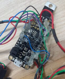
Keep in mind the Feather has multiple ground and power pins to connect to as marked in the pictures. There are enough pins for each wire to have its own.

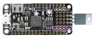

Step 1: Place the MOSFET into pins shown in picture and make sure the text points up. Bend the MOSFET pins so it lays flat and solder in place, then trim excess length.

Step 2: Cut a small piece of wire, about 1.5in, and solder one end to the pin on the left of the topmost MOSFET pin. Solder the other end of the wire to pin D13 as shown in the diagram.

Step 3: Take one of the 4 Circuit PicoBlades and cut the wires about 2" from the plug end. This will be the motor controller's connection to the Feather. The wire from pin 1 on the PicoBlade will be soldered to the center MOSFET pin. Pin 2 on the PicoBlade will be soldered to pin 12 on the Feather board. The wire from pin 3 can be soldered to any of the GND (ground) pins on the board. Lastly, the pin 4 wire can be soldered to the A0 pin on the Feather.

Step 4: Take the 2 Circuit PicoBlade connector and cut 2" from the plug side. This will be the E-stop connection. Solder 1 wire from the E-stop connector to the pin above the leftmost MOSFET pin. Solder the other wire to one of the ground pins. It doesn't matter which wire from the PicoBlade connects to the MOSFET verses which connects to ground.

Step 5: Bridge each of the MOSFET pins to the corresponding pins below the MOSFET as shown in the photo. Do this by adding solder to each of the pin holes and dragging the melted solder between them until there is a continuous solder joint across both pins.

Step 6: For the linear potentiometers, we will use the 3 Circuit PicoBlades. Again, cut the PicoBlade wire a about 2in from the plug side and solder the wire from pin 1 to a 3V pin on the Feather. Solder the pin 2 wire to A1 on the board and pin 3 will be soldered to ground. You will repeat this same process for the other linear potentiometer except solder pin 2 to A2.

Step 7: For the Rotary Encoder connection, we will use the 6 Circuit PicoBlade connecter. Cut the wires as short as possible but with enough length to reach all the joints, should be about 1.5in. We want the remaining half of the PicoBlade connecter wire to be as long as possible. The position 1 wire will be soldered to pin 10, the position 2 wire will be soldered to the SCK pin on the Feather. Connect pin 3 to the MI or "MISO" pin and pin 4 to the MO or "MOSI" pin on the board. Solder wire 5 to a 3V pin and wire 6 to a ground pin.

Step 8: Hot glue all wires in place to prevent them from breaking off. Avoid obstructing the holes in each of the four corners of the Feather board since they will be used to screw the board onto the frame.