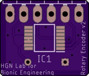
The hall effect rotary encoder that we will reference as the "encoder" measures what angle the leg is at in proportion to the thigh. The encoder needs to sit about 1 mm above a diametrically polarized magnet. The magnet sits in a casing that attaches to the end of the hex shaft so as the top joint rotates, the angle can be measured. The Hall effect encoder is a small black rectangular IC that is mounted on a custom PCB which can be ordered through the link on the parts list. You will have to solder the IC on the board yourself along with a through hole capacitor. More instructions can be found below. In addition we have a magnet holder Solid part that is available on GrabCad. Instructions on how to set up the magnet are below.

Components
| Item | Quantity | Link | Extra Information |
|---|---|---|---|
| Magnet Holder | 1 | GRABCAD page | |
| Custom PCB | 1 | Site | Recommend getting more |
| Hall effect rotary encoder | 1 | Site | Recommend getting a backup |
| Capacitor (0.1 uF) | 1 | Site | Highly recommend getting multiple backups |
Ordering the Encoder
The encoder can be ordered through OSH park. A link to our board is available in the parts list below and you will need to create an account to order it. We also have our schematics available to download on GitHub if you would like to make any changes We recommend ordering at least 3 for backups.

Setting up the PCB
Step 1: 3D print the Magnet Holder from our GrabCAD page.
Step 2: Solder the 0.1 uF capacitor to the PCB. Trim the ends of the capcacitor once it's soldered in the through holes. There are markings on the PCB showing where it will be placed. Make sure it is on the opposite side of the rotary encoder. The rotary encoder requires a specific distance from the magnet and placing the capacitor on the same side will interfere with that.
For help with soldering refer to the Soldering section in the Microcontroller page.

Step 3: Solder on the Hall Effect Rotary Encoder to the PCB making sure it has the correct orientation. There are a couple ways to solder on the rotary encoder. For either method you need to make sure each pin from the rotary encoder is lined up with an individual pad on the PCB. You can use tape to secure it in place while you solder. You also want to make sure that the pins are not connected to each other after soldering. You can use a multimeter to measure the current through each to check. If the current is the same, then you'll need to remove some of the solder at those joints.
The first method is simply soldering each individual pin to its corresponding pad on the PCB. You have to make sure that solder doesn't connect one pin to another. Since it is such a small component this will require a lot of precision.

The second method is to solder across all the pins on both sides of the rotary encoder. We do not want these pins to be connected so we will desolder across all the pins. This will remove most of the solder on these joints but will leave just enough between each pin and its respective pad.
Step 4: Solder each of the six wires from the 6 Circuit PicoBlade onto the PCB. You'll want to make sure the wires from the Feather are at least 6in long in order for the PCB to reach the magnet. Make sure each wire from the PicoBlade is soldered to the correct pin on the PCB. The images below show the corresponding pins. Hot glue the wires in place to prevent them from breaking off.


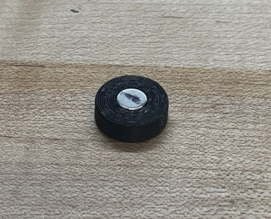
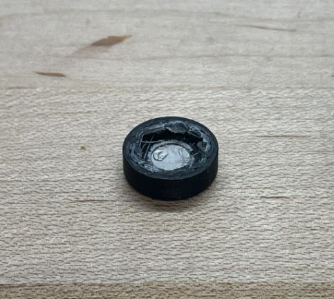
Step 5: Place a magnet in the Magnet Holder and hot glue it in place. Then place the Magnet Holder on the end of the hex shaft at the top of the frame. For more information on the magnet check out the next section.

Step 6: File the 4 points on each side so they are all smooth. Place the PCB in the rectangular hole at the top of the leg. Make sure the rotary encoder is facing the magnet and the capacitor is facing out. Plug the PicoBlade into the 6 circuit connector on the Feather Cover. Once you ensure that it works correctly, you can hot glue in place.

Setting up the Magnet
The Magnet Holder Solidpart is available on GrabCad. For the encoder to get accurate readings, the magnet must sit about 0.5mm to 1mm away from the IC. The magnet holder sits on the end of the hex shaft so that it is able to rotate with the knee joint. Depending on how your hex haft was cut, you may need to adjust the magnet holder file by making it longer or shorter. To test if it is a good distance, put the magnet holder with the magnet on the end of the hex shaft and the PCB over it. Upload the TestcodeEncoder from Github to the Feather and rotate the top joint. For help setting up the code, reference the Setting Up Arduino page. You should see the measurement change with the rotation of the top joint and you should not see any noise.
To setup the magnet holder, push the magnet in the circular cavity and use hot glue to glue it in place.
An important thing to note is that you want to be able to get continuous readings for the full 90 degrees the top joint can rotate. If you notice the angle jumps back to 0 or 360 degrees during this rotation, you will need to rotate the magnet holder until you get a continuous reading. If it jumps midway through articulation the leg will have unpredictable behavior because it will not know what angle it is positioned at.
In the main code for the leg, "IntergratedPIDController", in the defines sections of the main folder, is an offset value. Change this offset value to whatever value your encoder is reading when your leg is straight. The code will use this value to set the straight leg equal to an angle of 0 degrees.