
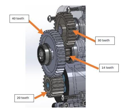
The transmission references the components that go from the motor to power the top joint, which acts as a knee. It was determined that to provide the necessary torque to the knee to walk (a fast movement) and climb stairs (a slow movement) the transmission needs to have a gear ratio of 260:1. The drill provides a transmission of 65:1, so the gear ratio from the motor housing to the top joint will need to be 4:1. We determined that a 4:3:1 transmission stage in series with the drill transmission would be the best option as it would give enough room between the motor and the top joint. The 4:3:1 ratio uses two gear stages of spur gears. The top joint sits on hex shaft, which is connected to the gears that power its rotation. The top joints range of motion is approximately 90 degrees and has end-stop built into the frame, preventing further rotation. A pyramid adapter is placed on the top joint to connect to a socket.
This transmission system has been tested for up to 65kg and shown to provide sufficient torque to the knee to prevent buckling and drive the knee in the swing phase.
Components
| Name | Quantity | Link | Extra Information |
|---|---|---|---|
| 3/8in hex hub | 2 | Site | |
| 3/8in steel hex shaft | 1 foot | Site | 1 foot, steel |
| 14 tooth gear | 1 | Site | |
| 20 tooth gear | 1 | Site | |
| 30 tooth gear | 1 | Site | |
| 40 tooth gear | 1 | Site | |
| Hex bearings | 4 | Site | |
| 0.063in hex spacers | 1 | Site | |
| 0.25in hex spacers | 1 | Site | |
| Machine Key | 1 | Site | |
| Shim stock | 1 | Site | |
| Bulldog pyramid adapter | 2 | Buy off Ebay | One goes on top joint, other goes on GCS |
| M6 55 flat head screw | 4 | Site | |
| M5 60mm screw | 6 | Site | |
| M4 55mm screw | 3 | Site | |
| M4 nut | 4 | Site | |
| Washer | 1 | Site | |
| M6 16mm left hang thread screw | 1 | Site | |
| 3/8 in. Hex Shaft Collar | 1 | Site |
Tools
| Tool | Purpose |
|---|---|
| Hex wrench set | |
| Rubber mallet | Getting shaft in place |
| 3D printer | |
| Pliers | |
| Tweezers | Placing hard to read nuts |
Transmission Assembly Instructions
Exploded Animation
Build
Step 1: 3D Print the Frame, Gear Housing, Top Joint, and Top Joint Spacers from our GrabCAD.
Step 2: Use a hacksaw to cut the hex shaft into one 108mm piece and one 50mm piece. It is important to be accurate with the measurements for the lengths of these shafts because it will make later steps significantly easier.

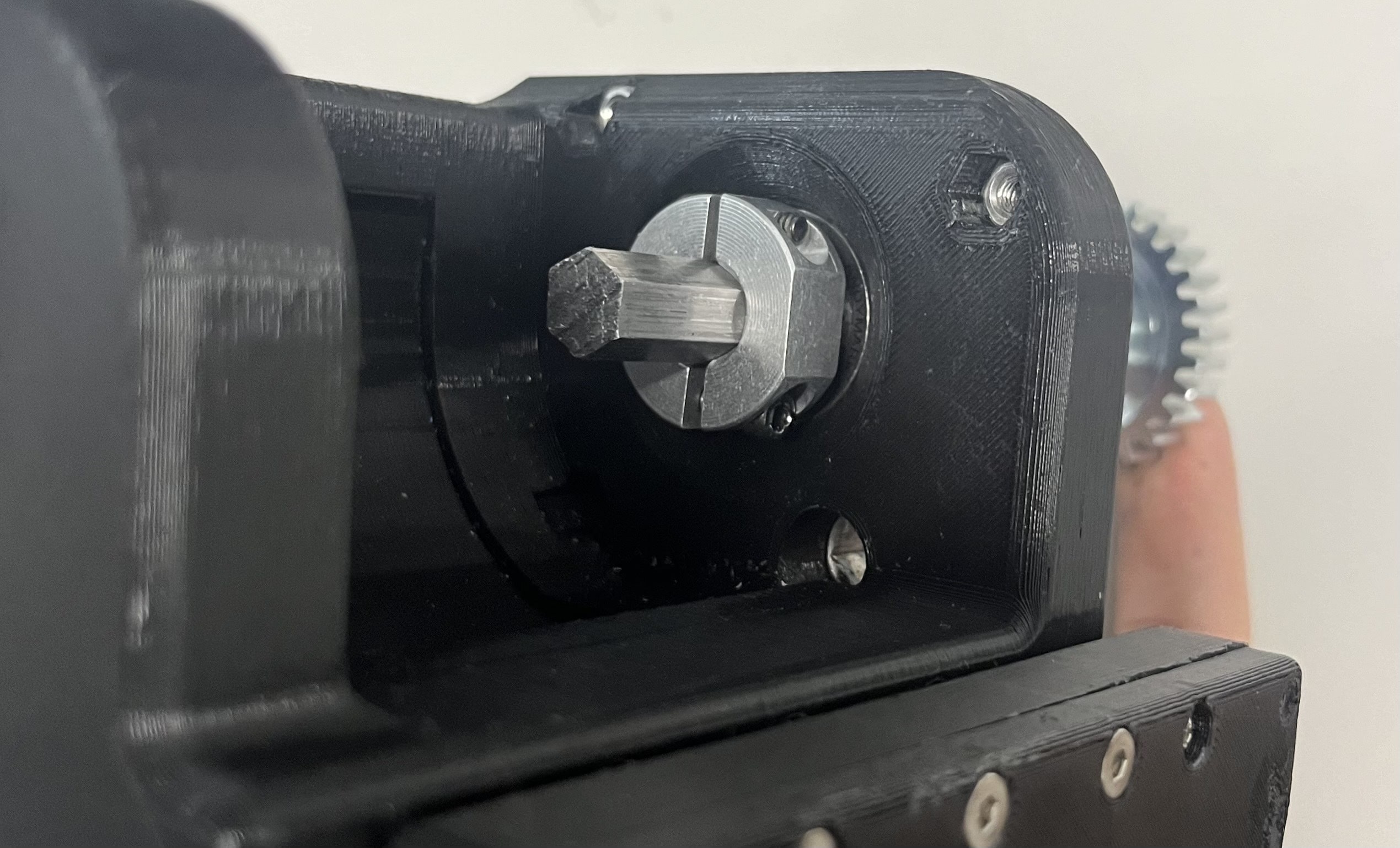
Step 3: Use Loctite to glue the 30 tooth gear onto one end of the 108 mm shaft so that the end of the shaft lines up with point where the hex cutout begins on the gear (see photo).

Step 4: On the short hex shaft use Loctite to glue the 14 tooth gear 8mm from the end of the shaft. Then glue to 40mm shaft on the other side so that the gears are touching.

Step 5: Attach the pyramid adapter to the top of the joint using four M6 55mm screws and four M6 nuts.

Step 6: Place the hex hubs on the sides of the joint and make sure they fit tightly. You may have to use a hammer or mallet to get one side to fit. Then, put six M5 60mm screws through the holes of the hex hubs. Use 5mm locknuts on the side of the joint facing away from the gears and tighten the screws.
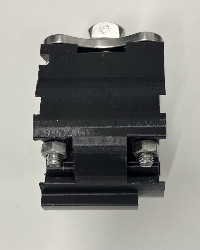
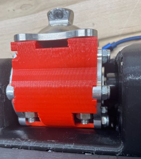
- The side of the joint facing away from the gear is distinguished by a small notch, as outlined in red below. This is best visualized by looking at a picture of the fully assembled top joint. In the image below, you can see there is a notch on the upper left side of the joint that is facing away from the gears. That is the side where you will put the lock nuts.
")

Step 7: Attach the 20 tooth gear to the drill transmission:
-
- Take 0.003in shim stock and cut a piece that encircles the inside of the gear and is the same width.
- Wrap the shim stock on the outside of the threaded end of the transmission and put the gear over it.
- Line up the notch on the gear to the notch on the thread.
- Push the rectangular key in the notch, mark where it sticks out and cut off the excess.
- Put the rectangular key back in.
- You may want to add a washer and screw at the end of the transmission to help keep the key in place.

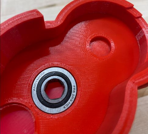
Step 8: Place bearings from the inside of the cavity for the two top holes on either side. For the bottom hole, place a bearing in from the outside.

Step 9: Put a bearing on the gear cover from the inside.
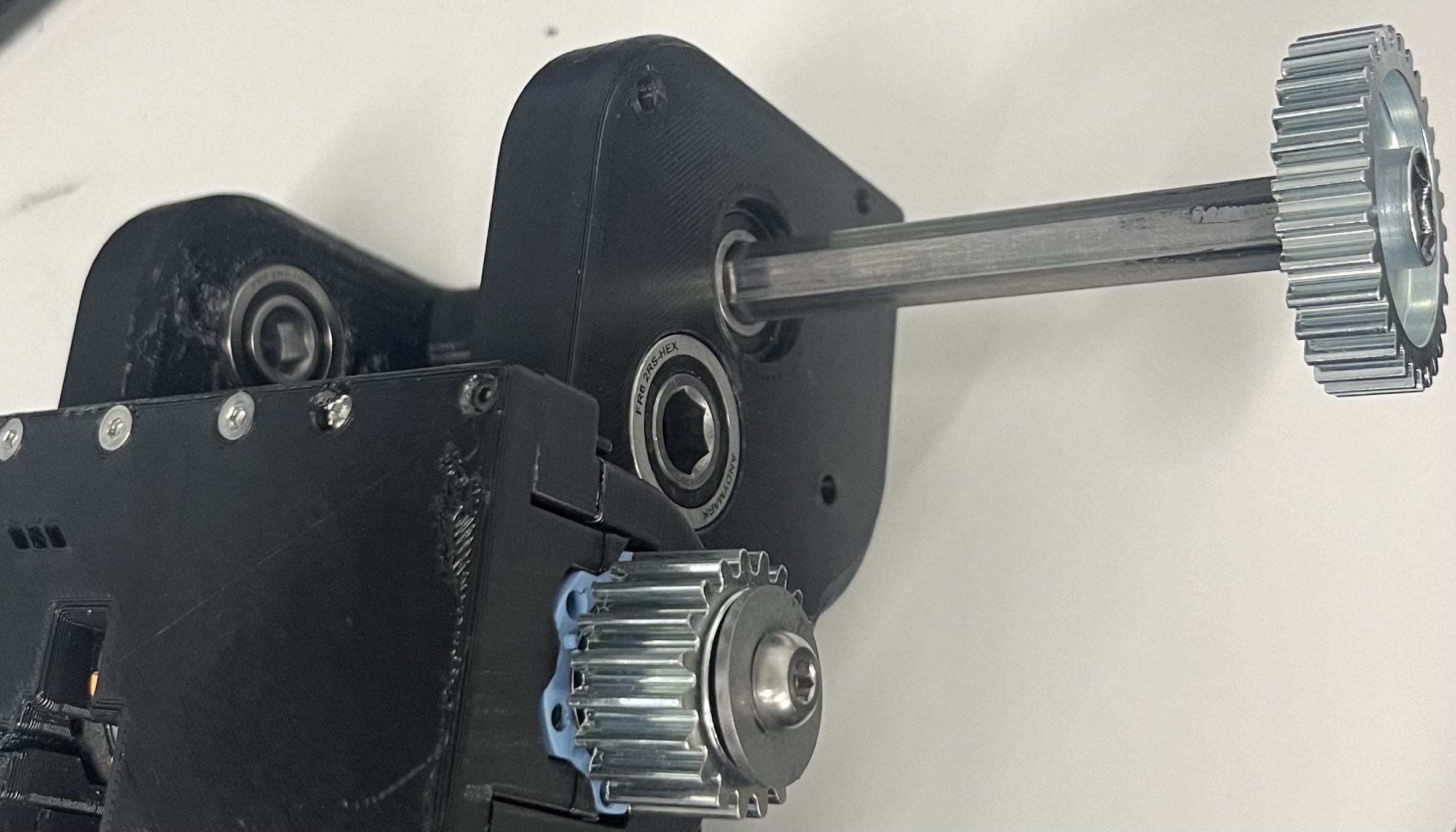
Step 10: Push the long shaft into the bearing from the outside. Push it in from the side where the end of the transmission is.
Step 11: Use the 2 spacers that were 3D-printed earlier and a hex two-piece shaft collar. The collar keeps the 30-tooth gear shaft in the place as well, but the two spacers decrease the potential of a loose collar impacting the results.

Step 12: Place the 3.5mm plastic spacer onto the shaft, then the collar. Don't tighten the collar yet.

Step 13: Put the top joint on the hex shaft while making sure that the orientation is correct so it is able to rotate 90 degrees. The notch should be pointing out the back and it will only rotate in one orientation.
Step 14: Put the 2.7 mm spacer in between the top joint and the frame on the other side. You may need to use tweezers to get it in place.
Step 15: Push the shaft the rest of the way through the bearings. You may need to use a hammer or mallet to achieve this. Stop when the gear is a few millimeters away from the frame. If the gear is touching the frame, this will cause increased friction and wear, so it is best to maintain some space. The other end of the shaft should stop 1-2 mm away from the flat surface of the frame.
- At this point, the joint should be able to smoothly rotate 90 degrees without hitting or interfering with any other parts of the system. If it can't, make sure your spacers are the correct size and are oriented correctly.

Step 16: Tighten the collar around the shaft. Once it is tightened, try to move the top joint horizontally left and right. The joint should not move at all. If it does, you may need to make adjustments to the spacers and collar because horizontal movement may cause issues in the future.
Step 17: Fit the small hex shaft onto the lower bearing with the 14 tooth gear on the inside side position touching the 30 tooth gear. The 40 tooth gear should touch the 20 tooth gear.

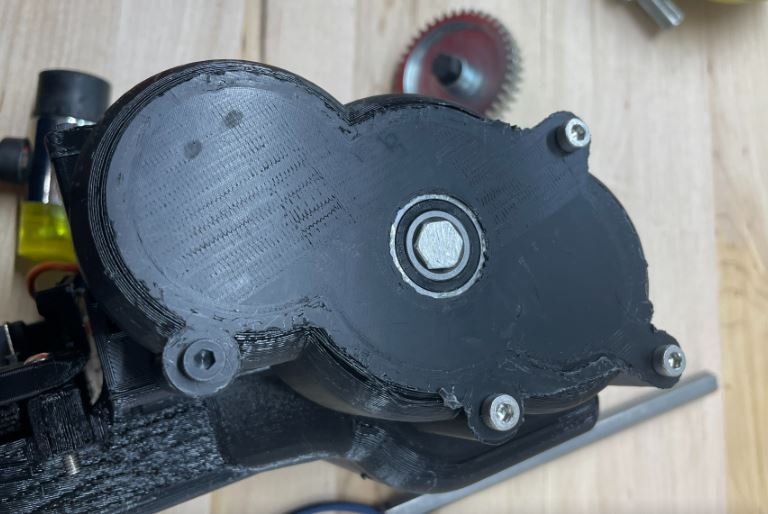
Step 18: Put the gear cover over the gears making sure the small hex shaft fits in the bearing. Use three M4 55 mm screws which go in the three topmost holes and nuts to fasten gear housing in place. To place the nut in the hole at the bottom of the cavity for the top joint use tweezers. Use one M4 45mm screw in the remaining hole (black screw in picture).
- A helpful option is to hot glue the nuts into the cavities to make placement and removal of the gear case an easier process. If you do this, ensure the hot glue doesn't interfere with the thread of the nut.
Testing
Before you have built the transmission you should have already tested the motor, therefore you can use the same motor test code the make sure you can move the top joint through the motor. Make sure to go at slow speeds because hitting the top joint against the end-stops can potentially damage the shaft or gears.
The next steps are moving to benchtop testing and PID tuning, which you can find in the Electronics and Control section.