
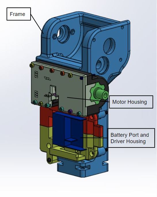
The motor system consists of the motor, battery, and motor driver. These components power the U-Build Bionic Knee. All of these components are taken from a Makita Cordless Drill. On the back of the frame there is a mount for the battery to slide into and a slot for the motor driver on the back. The Motor Housing is designed so that you can assemble and test the motor off of the frame before attaching it to the frame. The motor and transmission need to be held together very securely in the housing for the gears to mesh correctly.
You will also construct and attach the emergency stop (e-stop) and turn the motor on for the first time! Check out the videos and instructions below.
Components
| Name | Quantity | Link | Extra Information |
|---|---|---|---|
| Motor Housing Left | 1 | GRABCAD page | 3D Print(Reference GRABCAD for printing specs) |
| Motor Housing Right | 1 | GRABCAD page | 3D Print(Reference GRABCAD for printing specs) |
| Driver Housing Top | 1 | GRABCAD page | 3D Print(Reference GRABCAD for printing specs) |
| Driver Housing Bottom | 1 | GRABCAD page | 3D Print(Reference GRABCAD for printing specs) |
| Frame | 1 | GRABCAD page | 3D Print(Reference GRABCAD for printing specs) |
| Makita Drill | 1 | Ebay | Reference disassembly video to extract motor, transmission and driver. |
| M3 25mm screws | 4 | Site | Socket head preferred |
| M2 25 mm screw | 1 | Site | |
| M3 25mm screw | 4 | Site | |
| M3 60mm screw | 1 | Site | |
| M3 80 mm screw | 3 | Site | These are Phillips head |
| M4 25mm screw | 2 | Site | |
| M4 40mm screw | 1 | Site | |
| M2 nut | 1 | Site | |
| M3 nut | 11 | Site | |
| M4 nut | 3 | Site | |
| E-stop button | 1 | Site | |
| 20 Gauge wire | 1 | Site |
Tools Used
| Tool | Purpose |
|---|---|
| Hex wrench set | |
| Mallet | Placing screws |
| Dremel | Cutting key hole |
| Flat head screw driver | Drill disassembly |
Motor System Assembly Explanation
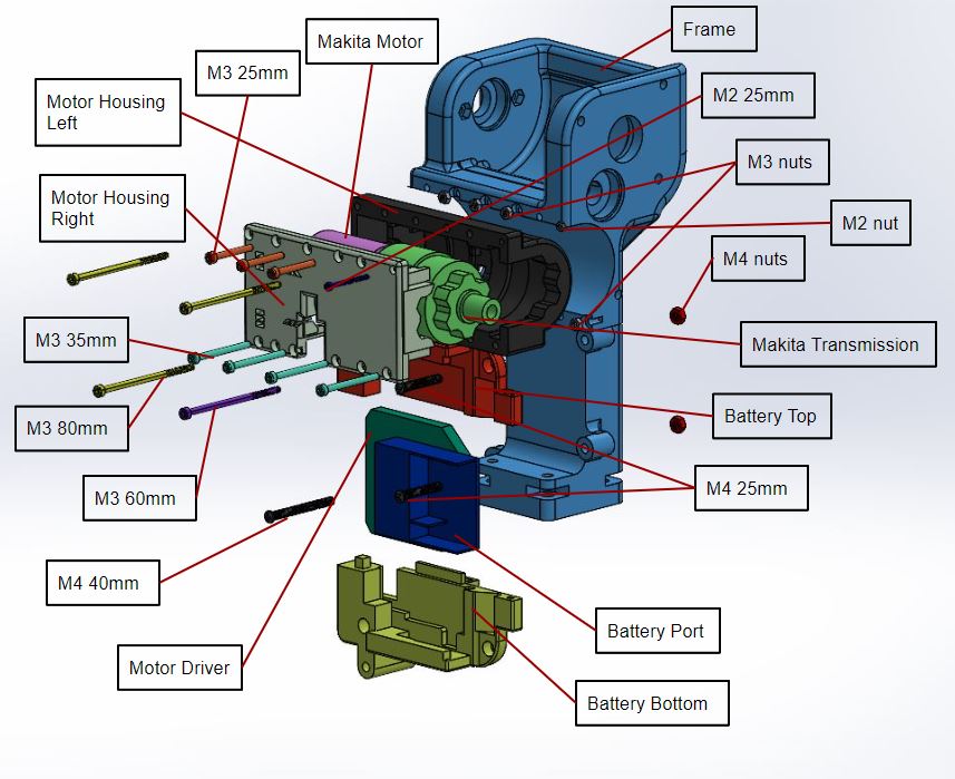
Exploded Animation
Wiring
Step 1: When you take apart the Makita drill, you will see that there are two large wires, pink and white, connected to the trigger. These wires need to be shorted for system to turn on. Cut these wires and solder them together. Use heat shrink to cover the solder joint.
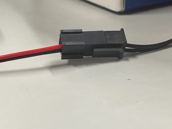
Step 2: Coming out of the driver there is a bundle of small multicolored wires connected to a white plastic connector. These wires can be cut off the attachment, and the white wire can be cut down as it will not be used.
Step 3: Take the 4 circuit PicoBlade receptacle and cut the wires to about 5". This length can vary depending on how much extra wire you want. The combined length of the PicoBlade wires and the motor wires needs to reach the other side of the Feather board, about 8".
Step 4: Solder the red motor wire to the pin 1 wire of the PicoBlade. This wire is the enable. In the code, 0 turns the motor on and 1 turns it off. This wire will be connected to the drain on the MOSFET. Make sure to use heat shrink over solder joint.

Step 5: Solder the blue motor wire to the pin 2 wire of the PicoBlade. This wire controls the direction of the motor. In the code, 0 makes it go clockwise and 1 makes it go counterclockwise. It is connected to pin D12.
Step 6: Solder the yellow motor wire to the pin 3 wire of the PicoBlade. This wire will be connected to ground.
Step 7: Solder the gray motor wire to the pin 4 wire of the PicoBlade. This wire supplies the power and is used to control the speed by varying the amount of power the motor receives. This wire goes to A0 which is the only in on the feather that has a Digital to Analog Converter (DAC) which is necessary for being able to vary the speed. To read more bout DAC's visit this site.
Build
Step 1: 3D print Motor Housing Left, Motor Housing Right, Battery Top, Battery Bottom, and the E-Stop holder. Here is the link to our GRABCAD page. Once everything is printed make sure to remove support material from each of the printed components.
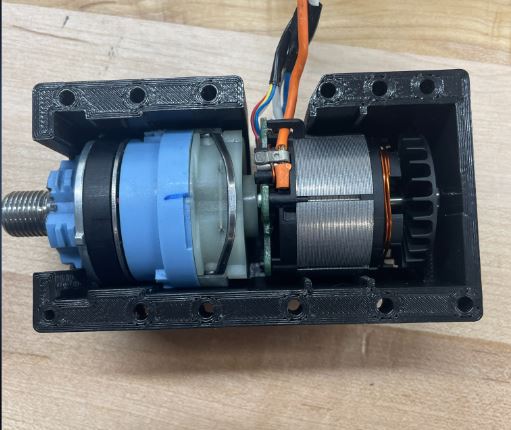
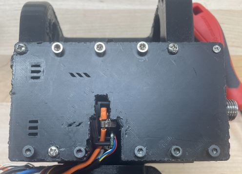
Step 2: Place the motor into the motor housing making sure it fits snug in place and both sides are able to close around it. Make sure the metal bar is facing up as shown in the picture.
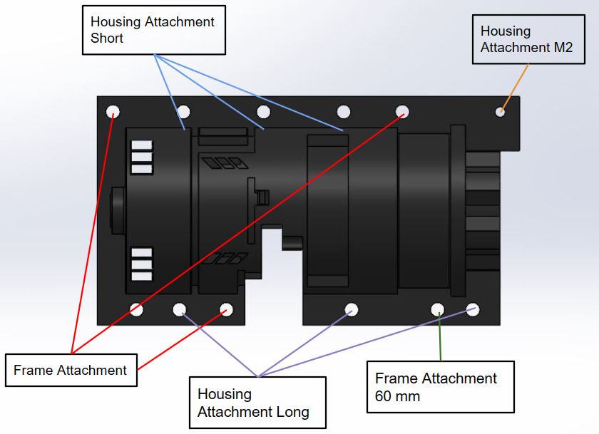
Step 3: Place 3 M3 25 screws through the motor housing in the holes marked in the diagram "Housing Attachment Short" with nuts. Place 3 M3 35mm screws with nuts in the holes marked "Housing Attachment Long".
Step 4: Place one M2 screw through the hole marked "Housing Attachment M2" with nut.
Step 5: Place the motor into the cavity in the frame.

Step 6: Mount motor onto frame:
-
- One at a time place an M3 nut in the front of the frame in the rectangular cavities associated with the holes marked "Frame Attachment" and place an M3 80mm screw through, making sure to tighten as you go
- In the remaining hole marked "Frame Attachment 60mm" place a nut in the corresponding hexagonal hole and screw an M3 60mm screw into it.
Step 7: Take one side of the battery housing and slide the driver and the battery port into it.

Step 8: Slide on the other side of the battery housing.

Step 9: Attach battery housing to frame:
-
- On the left side the frame, looking at it from the back, attach two M4 25mm screws and nuts. Make sure the nuts sit in the rectangular cavities.
- On the other side, screw in a M4 40mm screw and nut through the hole.

E-Stop Setup
To operate the motor you must connect the E-stop. Follow the instruction to set it up. In our design we implemented an emergency stop button. The emergency stop is between ground and source on the MOSFET. It was put here to avoid having to reboot the microcontroller after the button was pressed.
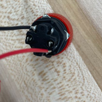
Step 1: Cut two 5 foot strands of 20 gauge wires. Strip end of wires and solder one end of each wire to position 1 or 3 on the E-Stop.
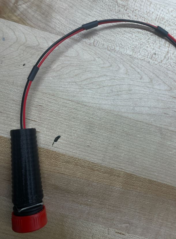
Step 2: Feed wires through the bottom hole of the E-Stop Holder and push e-stop into the top.

Step 3: Cut pieces of heat shrink and feed onto loose ends of wires to hold them together. This is to keep the wires neat and prevent them from tangling. Space out the pieces and use a heat gun to keep them in place.
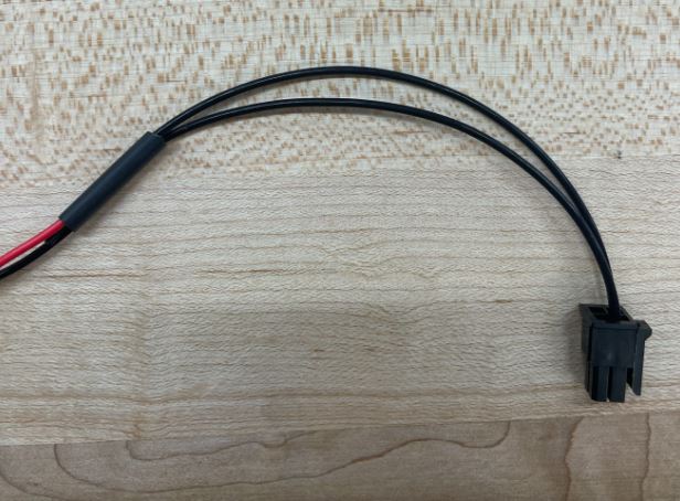
Step 4: Solder loose ends of wire to 2 wires on a socket 4 position connector. Cover each solder joint with heat shrink. Make sure the wires positions line up with the wires on the E-stop connector on the feather. Cut off the extra 2 wires. Which wires go to the MOSFET and ground do not matter.
Testing
Once this system has been built and the motor and E-Stop are connected to the microcontroller, we highly recommend running our test code to ensure everything is working properly. When uploading code, make sure to have the drill battery unplugged or the E-stop pressed to protect the other electronics until the upload is complete.
On GitHub, download Motorfunctiontest in the test code folder. The following video explains expected results along with an explanation behind the motor library.