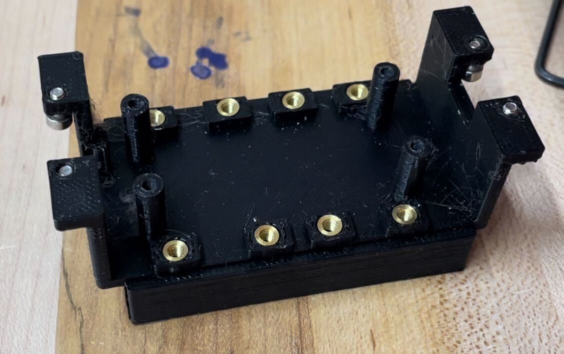
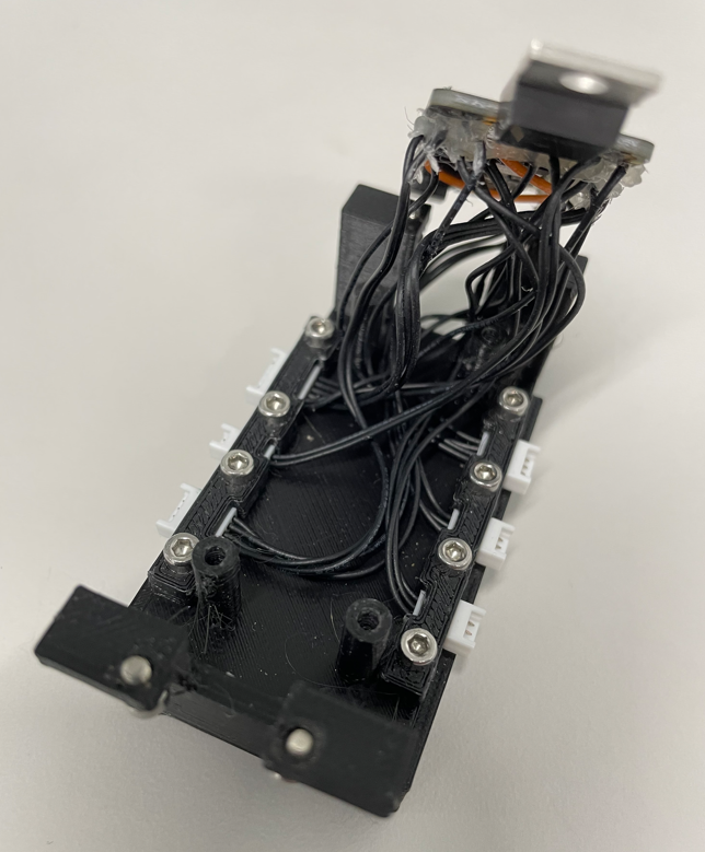
The frame of the U-Build Bionic Knee is the structure that supports the weight of the user. It is also the structure to which additional components and sensors are attached. This section will explain the initial setup of the frame and attaching the microcontroller.
Components
| Item | Quantity | Link | Extra Information |
|---|---|---|---|
| Frame | 1 | GRABCAD page | |
| 3D Print Filament | 2 Rolls | GRABCAD page | |
| M2.5 Heat Set Inserts | 12 | Site | |
| M2.5 5mm Screws | 12 | Site | |
| M2.5 10mm Screws | 4 | Site |
Tools
| Soldering Iron | Placing heat set inserts |
|---|---|
| Tweezers | Placing heat set inserts |
| 3D printer | |
| Hex wrench set |
Frame Assembly Video
Heat Set Insert Tips
Heat set inserts are a good way to connect components of a 3D printed assembly. They form a strong bond to the 3D print material and create a secure hold for screws. We use these multiple times throughout this project.
Here is a short tutorial on how to install a heat set insert.
You can use tweezers/pliers to help hold the heat set insert in place. If the 3D printed supports aren't completely removed, some melted material may fill the center of the heat set insert as you install them. If this still happens or holes are too shallow to screw on the feather cover, then you can use a drill to remove excess material. Make sure drill bit is small enough to only remove 3D printed material and not damage the threads on the heat set insert. To prevent this from happening, place a screw in the heat set insert before installing to block any melted 3D print from filling the hole.

Frame Assembly
Step 1: Print the Frame, Feather Cover, Feather Cover Lid Left, and Feather Cover Lid Right parts. Here is the link to our GRABCAD page. Once everything is printed make sure to remove support material from each of the printed components.
Step 2: Install M2.5 heat set inserts into each of the eight holes on bottom of the Feather Cover. Refer to the Heat Set Insert Tips section for help with this step.

Step 3: Place each connector into its specific slot on the Feather Cover as shown below. Using M2.5 5mm screws, screw the Feather Cover Lids over the slots to hold the connectors in place. Note that each slot and lid are sized for a specific size of PicoBlade. Make sure the orientation for each lid is the same as pictured.


Step 4: Place the Feather board on top of the four corner supports of the Feather Cover. Make sure the board lays flat and each hole is cleared of any wires. Use M2.5 10mm screws to secure the feather to the supports.
Step 5: Install four M2.5 heat set inserts in the holes on the front of the frame.

Step 6: Screw the assembled Feather Cover into the frame's heat set inserts using M2.5 5mm screws.

Step 7: Screw the assembled Feather Cover into the frame's heat set inserts using M2.5 5mm screws.

