
The Ground Contact Sensor (GCS) determines if the user is loading the leg (e.g. during stance phase of walking) or if the leg is unloaded (e.g. during the swing phase of walking). Using the GCS, the U-Build Bionic Knee knows when to move and when to stay static to support the patient. No matter the terrain, as long as the patient applies a strong enough load to create a moment about the hinge of the GCS and close the wave spring, the knee will react how the patient needs.
The GCS is built using a spring loaded hinge mechanism. When the foot is placed on the ground, load applied by the user generates a moment about the hinge and closes the hinge mechanism. The change in angle of the hinge is measured by two linear potentiometers. A linear potentiometer is a device that converts a change in position to a change in voltage. This change in voltage can be measured by a microcontroller or other device. To learn more about linear potentiometers check out this site.
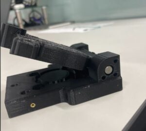
When the foot is unloaded, a spring opens the hinge mechanism. Again, the change in angle of the hinge is measured by the linear potentiometers. It is constructed from a top and bottom plate that form a hinge. The top plate connects to the frame through a 36mm bolt pattern. The bottom plate uses the same bolt pattern to connect to a pyramid adapter. A wave spring is placed between the two plates to generate a restoring force. An end stop is placed opposite of the hinge to set the rest length of the spring. The GCS is designed to open and close a small distance and is unnoticed by user but can still be measured by the potentiometers. Two potentiometers are used so that accurate measurements of ground contact can be obtained when load is directed through the device in a number of orientations (e.g. heels strike, or toe off).

Components
| Name | Quantity | Link | Extra Information |
|---|---|---|---|
| GCS Top Plate | 1 | GRABCAD | 3D print(Reference GRABCAD for printing specs) |
| GCS Bottom Plate | 1 | 3D print(Reference GRABCAD for printing specs) | |
| GCS End Stop | 1 | 3D Print(Reference GRABCAD for printing specs) | |
| GCS Linpot Holder | 2 | 3D Print(Reference GRABCAD for printing specs) | |
| Linear potentiometer | 2 | Site | |
| Dowel pin | 1 | Site | |
| M2 5mm screw | 2 | Site | |
| M3 14mm flat head screw | 4 | Site | Not necessary to have a flat head, but preferable to reduce snagging |
| M2 Heat Set Inserts | 2 | Site | |
| M3 Heat Set Inserts | 4 | Site | |
| Pyramid Adapter | 1 | ebay | Some come with screws, if not or not correct size order next item |
| M6 16mm flat head screw | 4 | Site | |
| M6 30mm flat heat screw | 4 | Site | |
| M6 nut | 8 | Site | |
| Wave Spring | 1 | Site |
Tools List
| Tool | Purpose |
|---|---|
| Soldering iron | placing heat sets |
| 3D printer | |
| Hex wrench set | |
| Clamp | closing GCS to place end stop |
| Mallet | Placing dowel pin |
| Hot glue gun | gluing linpot holders |
| Pliers | general use |
GCS Assembly Instructions
Exploded Animation
Wiring
Step 1: Take one linear potentiometer and one of the 3 circuit PicoBlade receptacles. For the linear potentiometer on the front of the leg, or the one closest to the Feather, trim the wires to about 2in. Trim the PicoBlade wires so they are about 1.5in. These lengths can vary depending on how much extra wire you want.
Step 2: Splice the yellow linear potentiometer wire with the pin 1 PicoBlade wire. Make sure to use heat shrink over the soldering joint. This is the live wire or the power wire, these will be connected to three volts.
Step 3: Splice the red linear potentiometer wire with the pin 2 PicoBlade wire. The red wire is the logic wire and can be connected A1 or A2. This will allow the potentiometers to send input data back to the Feather.
Step 4: Splice the green linear potentiometer wire with the pin 3 PicoBlade wire. The green wire will be connected to ground.
Step 5: Repeat steps 1-4 for the other linear potentiometer. However, cut the wires for the second linear potentiometer to about 6in instead of 2in since it's farther from the Feather.

Build
Step 1: 3D print GCS Top Piece, GCS Bottom Piece, GCS End Stop, and two GCS Linpot Holders. Here is the link to the GCS GRABCAD page. Make sure to remove all support material from each component.
Step 2: Place four M3 heat sets into holes on end of GCS bottom piece.
Step 3: Place two M2 heat sets into holes on front and back of GCS bottom piece.
- For tips on installing heat set inserts, go to the Heat Set Insert section on the Frame page.

Step 4: Attach a pyramid adapter to outside of the GCS bottom piece with screws going from outside to inside.

Step 5: Attach top and bottom piece together by placing the dowel pin through the large thru-hole on end of each piece forming a hinge.
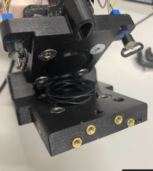
Step 6: Fasten the GCS to the frame:
- Line up holes on the top piece to holes on the frame with the hinge end on the right side, looking at the frame from the front.
- Place a nut in one of the cavities on the sides of the bottom of the frame.
- Take an M6 30mm screw and push it from the inside of the GCS top piece into the hole and up to the nut to tighten.
- Repeat for all screws.

Step 7: Place the liner potentiometers into the rectangular holes on anterior and posterior sides of the leg with wires closest to the hinge.

Step 8: Push the linpot holder onto the end of the shaft.
Step 9: Screw an M1.6 nut all the way up the thread.
Step 10: Pull down the linear potentiometer holder down onto the nut so the nut fits inside the hexagonal cavity. Hot glue the nut in place.

Step 11: Place the wave spring in the circular recess and close the GCS (a clamp might be necessary).
Step 12: Place the end-stop by ensuring the lip goes over the top piece and screw M3 14mm screws through the end-stop into the heat set inserts.

Step 13: Place an M2 5mm screw through oval hole in linpot holder and into heat set, ensuring the screw is able to move around the cavity freely, so that the shaft of the linear potentiometer doesn't break due to bending.

Step 14: Wire both linear potentiometers and plug them into the 3 circuit connections on the Feather Cover. More details on wiring are in the section below.


Testing
Before moving on to another system, we strongly recommend wiring just the potentiometers and running the linear potentiometer test code on Github. You should make sure that you are able to get two lines of numbers in the serial monitor that react to when the GCS is compressed and uncompressed.