
For the U-Build Bionic Knee, we have not yet designed a 3D printable foot, so you will need to buy the components off of eBay. This section has been developed to provide options for testing the device, including a I-Walk and benchtop setup.
The benchtop setup allows easy testing of the knee. It consists of a piece of aluminum or wood with holes drilled in the mount a female pyramid adapter to. Then, the pylon and tube clamp pyramid receiver attaches to the top of the leg.
The I-Walk is included for testing to be performed by someone without an amputation. The I-Walk device needs to be modified so that you can attach a female pyramid adapter to the male pyramid adapter on the top of the leg. This involves using a bandsaw and drill press to machine a plate that can screw onto the bottom of the I-Walk.
We have broken this page into Foot, I-Walk, and Benchtop sections with instructions on what to buy and how to assemble.


Components
| Item | Quantity | Link | Extra Information |
|---|---|---|---|
| 4 Hole Female Socket Adapter | 2 | eBay | Reference instructions for help buying prosthetics components |
| Pyramid receiver to Pylon | 2 | eBay | Reference instructions for help buying prosthetics components |
| Tube Clamp to Male Adapter | 1 | ebay | Reference instructions for help buying prosthetics components |
| Tube Clamp Adapter(female) | 1 | ebay | Reference instructions for help buying prosthetics components |
| Prosthetic Foot | 1 | eBay | Reference instructions for help buying prosthetics components |
| I-Walk | 1 | Site | |
| Aluminum Sheet Stock | 1 | Site | |
| Aluminum Cylinder Stock | 1 | Site | |
| M6 14mm Flat Head Screws | 4 | Site | |
| M6 20mm Flat Head Screws | 9 | Site | |
| M10 25mm Flat Head Screw | 1 | Site |
Tools
| Item | Purpose |
|---|---|
| Bandsaw/hacksaw | Cutting aluminum |
| Drill press | Putting holes in aluminum |
| Tap handle | |
| 6mm Tap | |
| Hex wrench set |
Benchtop
For this section you will need to buy the following parts off eBay:
- 4 hole female socket adapter
- Pyramid receiver to pylon
- Tube clamp to male adapter
These precise names might not have many search results, but using keywords like "Prosthetics components", "Prosthetic pylons", and "Pyramid adapters" tend to have good search results. Look for items that look like the items below. Many people will not list the technical names so use these images as a reference. You may find the tube clamp and pyramid receiver already assembled, so we included a picture of that as well.

4 Hole Female Socket Adapter

Pyramid Receiver to Pylon

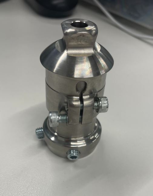
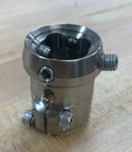
Tube Clamp to Male Adapter

Tube Clamp and Pyramid Receiver Assembled

Step 1: Cut a piece of the aluminum stock with a band saw so that it is slightly wider than the 4 Hole female socket adapter, which is about 52mm wide. The piece needs to be long enough to to clamp on both sides. A piece that is 150mm will be sufficient.
Step 2: Cut 4 holes with a drill press that correspond to the holes on the pyramid adapter. Most pyramid adapters use M6, so drill holes slightly larger, but confirm the size of your pyramid and its holes before drilling.

Step 3: Use four M6 screws to attach a pyramid adapter to the aluminum sheet. Screws need to be long enough to secure the adapter.


Step 4: Slide pyramid receiver to pylon into the tube clamp to male adapter. Tighten the screws on the side of the tube clamp to secure.
Step 5: Put the male end of the previous assembly into the female adapter on the aluminum sheet and tighten the screws on the side. Only tighten and release two of the four screws on the female adapter to attach and detach the male end.

Foot Attachment
All of the components for the foot will have to be purchased off of eBay (except the shoe you wish to use). It can be confusing to determine what to buy, so if you are not sure if you are getting the right parts, send us an email with links to all the items you are looking to purchase and we can give our input. In The U-Build Bionic Knee we use a footshell. The footshell is not necessary, but these can also be found on eBay if you wish to. The prosthetic foot will have a male adapter on the top. For this assembly you will need a prosthetic foot, tube clamp adapter (female), and pyramid receiver to pylon. Pictures of these components are below. If you do not get results with these names on eBay, try the recommended keywords from the Benchtop section.
Prosthetic Foot

Tube Clamp Adapter(female)
Pyramid Receiver to Pylon
Step 1: Slide pyramid receiver to pylon into tube clamp adapter and tighten screws on the side of the tube clamp.

Step 2: Slide the female end of the assembly onto the male adapter of the prosthetic foot and tighten the side screws. Each end is identical so the orientation of the assembly does not matter.

Step 3: Attach the foot onto the powered knee using the male pyramid adapter on the bottom of the GCS. If you are using a foot-shell you can slide your foot into this. Then, put a shoe on the foot.

I-Walk
To be able to attach the I-Walk to the knee, you will need to mount a 4 hole female socket adapter on the bottom. However, there is no way to do this on the I-Walk as it comes, so you will need to create a plate that mounts on the bottom of the bypass that can accept a pyramid adapter. The only prosthetic component you will need for this is a 4 hole female socket adapter that you can buy on eBay. Please reference the picture of this component in the benchtop section. We recommend getting two adapters, but you can trade the same adapter between the benchtop and bypass.
The completed bypass component will look like either of the two images below:


It is important to note that the majority of this process requires access to and the ability to operate a drill press. If you don't know how to use a drill press, these resources might be helpful:
- https://youtu.be/Q2gv59aeMAQ?si=fIPLpEfZvCrMhiWl
- https://www.toolnerds.com/how-to-use-a-drill-press/
Part 1: Aluminum Plate
Start by accessing the SolidWorks files of the drawing and part for reference during this process. The SolidWorks files can be found in the Grab CAD.
We recommend printing the SolidWorks drawing to-scale and taping it onto the aluminum as a guide. The scaled pdf can be found here: iWalkPlate
For this part of the process, you will need a piece of stock aluminum about 1/5 in thick that is large enough to cut 154 x 110 mm rectangle out of it.
Step 1: Cut out all holes according to the drawing through the sheet of aluminum.
- Countersink all M6 holes.
-
- If you've never countersunk a hole before, this video might be helpful: Countersink Tutorial
- Once you feel like you have countersunk it effectively, test it with the screws to see if they are flush with the surface.
- Tap each of the four smaller 5mm holes for an M6 screw.
- If you've never tapped a hole before, here is an in-depth video on the process: Tapping Tutorial
Step 2: Once the holes have been cut, you have two options for shape of your bypass:
- Simple Rectangle: If you cut out a 154 X 110 mm rectangle from the aluminum, it will work with the I-walk.
- Curved Shape: If you want the piece to resemble one that is normally used and to be smaller and lighter, you can cut out the aluminum according to the drawing.
Methods of cutting: All actions in this process have been created anticipating only a hacksaw tool will be available. A hacksaw will be sufficient for this process, but you may find it time consuming or tiring. If other options are available, all machining of the aluminum can also be done on a mill, CNC machine, waterjet, etc.

")
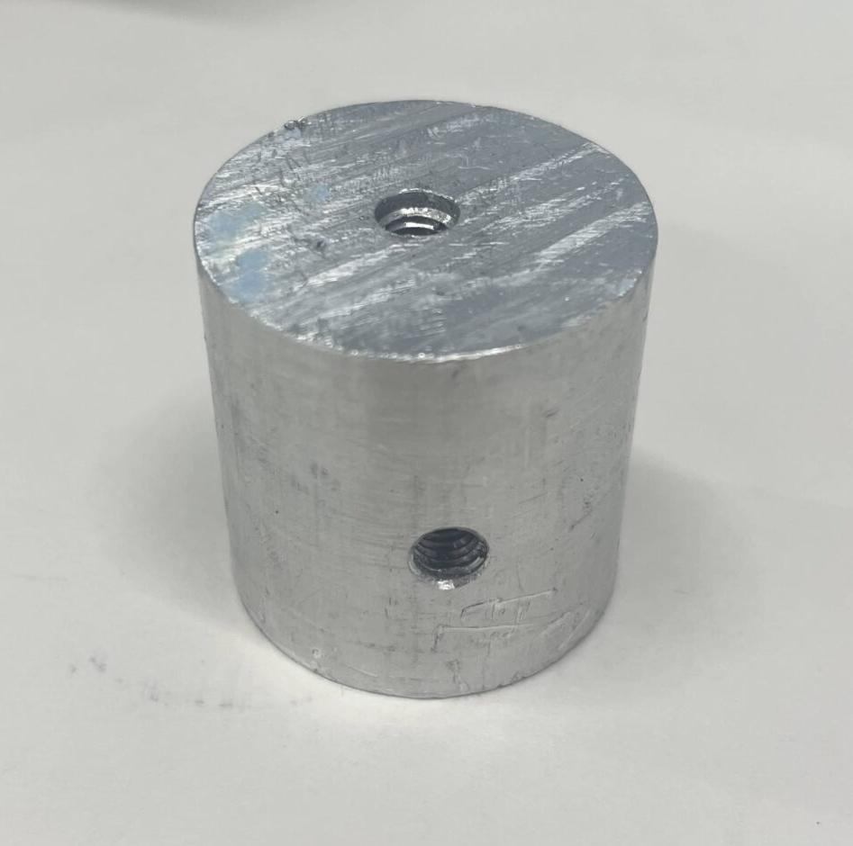
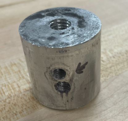
Part 2: Cylindrical Supports
For this part, you will end up with three aluminum cylinders for the bypass: two thin 20 mm diameter cylinders and one wider 35 mm diameter cylinder.
Thin Cylinders:
Step 1: Using a hacksaw, cut two 2.7in long pieces of aluminum out of the thin cylindrical stock.
Step 2: On one end of the cylinder use a drill press to cut a 5mm wide hole about an inch down.
- Find the center. This hole will need to be centered in the middle of the cylinder top. There are several options for finding the center. It is also okay to guess. One option is to 3D print the centering caps found on GrabCAD, place them on top of the cylinder, and mark the center using their guide.
- Use a centering drill bit and drill a few millimeters into the cylinder creating a funnel shape towards the center.
- Use a 5 mm drill bit and drill a hole into the cylinder stopping about an inch down.
- To determine when to stop, you can put a piece of tape on the drill bit approximately an inch up. This measurement does not have to be very specific, just long enough that the screw can go completely in.
- Repeat for the second cylinder.

Step 3: Using the same process as above, cut another 5mm hole going through the side of the cylinder 50mm down from the surface where you cut the last hole. This hole can go all the way through. Repeat for the second cylinder.

Wide cylinders
Step 1: Use a hacksaw to cut a 36mm long piece from the wide 35mm diameter stock aluminum.
Step 2: Use a drill press to cut a 5mm hole going down approximately an inch.
Step 3: Cut another 5mm hole through the side of the cylinder 16mm down from the surface where you cut the last hole.
Step 7: Use a tapping tool to tap all six holes for an M6 screw.

Part 3: Assembly
Step 1: Put the two thin cylinders in the two holes at the front of the I-Walk with the surface that has the hole drilled into it facing outward.
Step 2: Put the wide cylinder into the wide center hole with the surface of the cylinder that has the hole drilled into it, facing outward.
Step 3: Line up all of the side holes with the corresponding holes in the I-Walk.
- The wide cylinder fits very tightly into the hole, so you may need to use a wrench or another tool to shift the cylinder so that the holes line up.
- Use a M6 20 mm screw for each of the three side holes to keep the cylinders in place.


Step 4: Place plate on top of the cylinders and line up the holes. Place three M6 20 mm screws through the plate into the small and wide cylinders.
")
Step 5: Mount a 4 hole female socket adapter over the large cylinder and screw into place using four M6 14mm screws.
